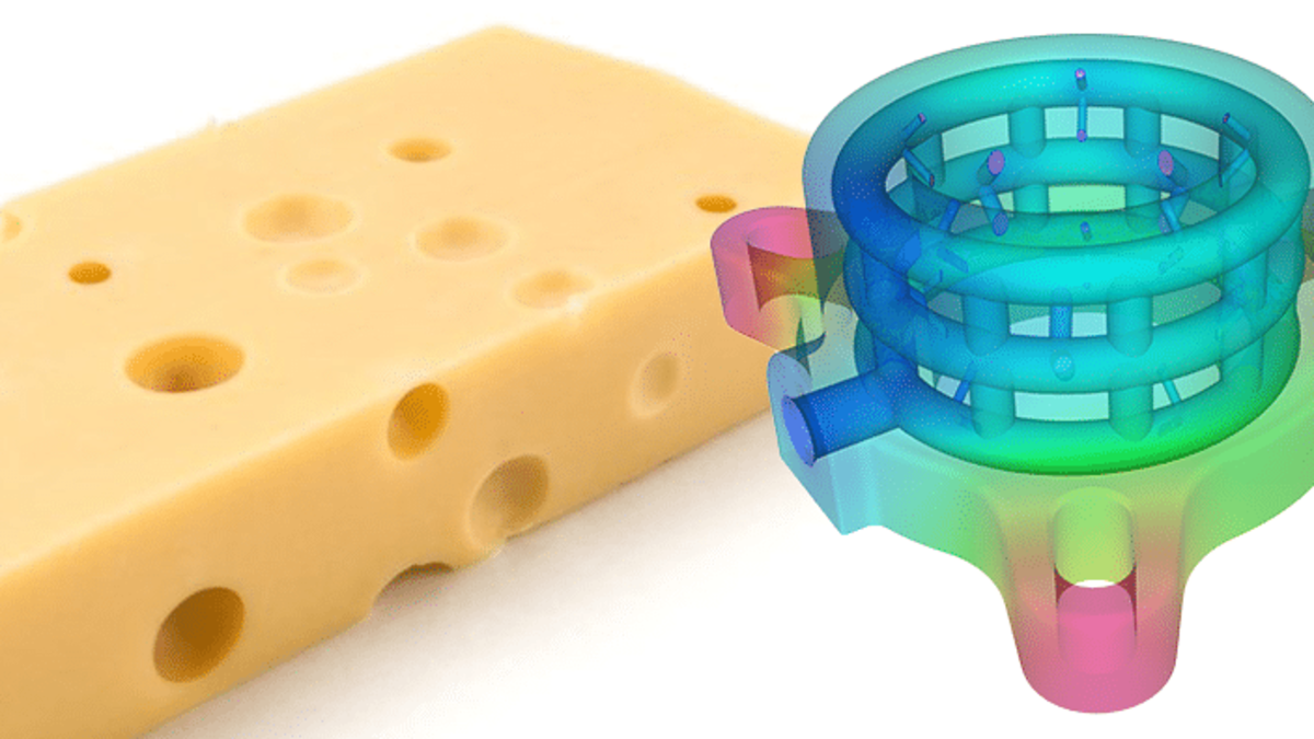
What do injection molds have in common with Swiss cheese? It's the holes that count!

Why the heat often has to go away quickly and evenly
In injection molds, the heat generated during cooling of the plastic melt must be dissipated. This requires a complex network of cooling holes that perforates the mold like a cheese. FEM and CFD simulations provide perfect insights for the optimal design of relevant injection molds.
Unlike cheese, the injection mold needs to hold the cooling water, while a cheese only needs to taste good. The cooling water must dissipate heat from the entire component as quickly and uniformly as possible, otherwise major distortion in the workpiece or long cycle times will result. The required cooling holes are therefore strongly dependent on the geometry of the injection mold.
Curved channels would be advantageous, as this results in lower pressure losses.
Now, however, drills that drill around corners or make a nice curve have not yet been invented, and so straight holes have to find each other and be closed at the ends by plugs.
This is where 3D printing offers new, constructive possibilities. The cooling holes for dissipating heat here can be of any geometry and interconnected. Although the rough surface must also be reworked here in the contact area with the injection mold, it does no harm in the cooling channels. A perfect playing field for FEM and CFD simulation. Unfortunately, we are not allowed to show relevant projects we are currently working on. But the principle can be demonstrated with a comparable example.
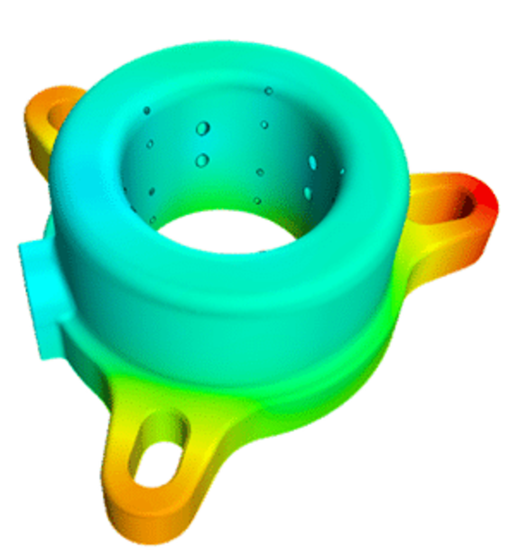
The demonstrator shown here is a 3D printed component through which air flows and is actually used to remove chips from the workpiece during production.
The issue is somewhat different from that of the injection mold and heat dissipation: How do you get an equal mass flow around the circumference of the nozzle? This is more of an equal distribution problem, which can also be ideally calculated and optimized with CFD.
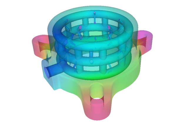
In the following, however, let us concentrate on the dissipation of heat: Assuming that heat is generated uniformly in the ring, what effect does a flow of cooling water have on the temperature in the component?
You can clearly see that the temperature is lower at the point where the cooling water is supplied than at the opposite end.
How large the effect is depends, of course, on the boundary conditions and the geometry.
All relevant effects can be precisely described in the simulation model in the same way as in the injection mold, including the distribution of the volume flow to the individual channels, which depends on the pressure drop.
For example, the volume flow rates of the water exiting the bores are very different, even though there are only two bore diameters.
Due to the heating and cooling cycles, stress amplitudes occur in the mold, which influence the service life. This is also referred to as thermal shock. This can also be calculated with the help of simulations and compared with the requirements.
If the physical causes of a problem are identified, targeted countermeasures can be taken, i.e. the component can be optimized.
If you also have the requirements to cool components as homogeneously as possible, we would be pleased to advise you without obligation.
Your Stefan Merkle


