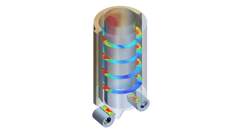
A lot of hot air - for nothing? CFD simulation shows why the nacelles of wind turbines do not always get rid of their heat without problems
We all know it from our childhood playing with electric trains: The transformer gets quite warm and sometimes it burns out.
It is similar with transformers of wind power plants, they also get warm.
Only the amount of heat is somewhat higher and the damage is greater...
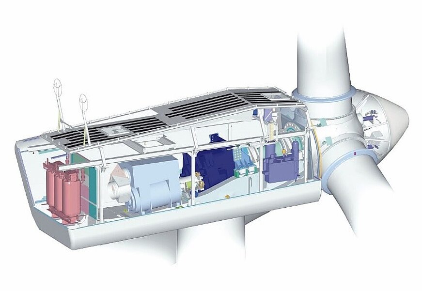
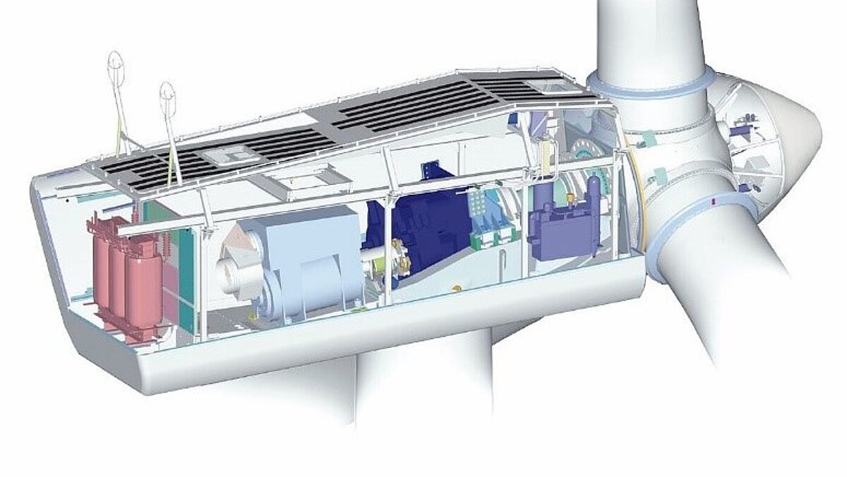
The transformer unit of a wind turbine is located in the rear part of the nacelle and has its own cooling air supply.
During operation, the power losses in the coils cause the transformer to heat up and the resulting heat is released into the ambient air.
In order to maintain the permissible operating temperature of the transformer elements while ensuring a non-critical level of room temperature, the cooling must be sufficiently dimensioned. In addition, if the transformer unit consists of several closely arranged coils, the influence of radiation cannot be neglected and individual points with increased temperatures may occur.
If the cooling is only done by free convection and there is no influence of neighboring coils, an analytical estimation of the cooling properties may still be sufficient.
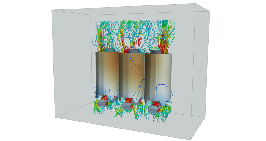
On the other hand, in the case of active cooling of the transformer by means of several fans, an analytical estimate is no longer possible due to the complex flow field. In this case, a thermal analysis of the cooling by means of a numerical flow simulation is appropriate. The use of CFD simulation (Computional Fluid Dynamics = flow simulation) offers the advantage that the complete transformer space in the nacelle including radiation can be taken into account.
The fans mounted on the underside of the transformer draw air from the environment into the nacelle. The positioning of the fans is such that the cooling air is blown directly into the individual annular gaps of the coils to allow sufficient cooling. The heated air is discharged back into the environment at the top of the nacelle.
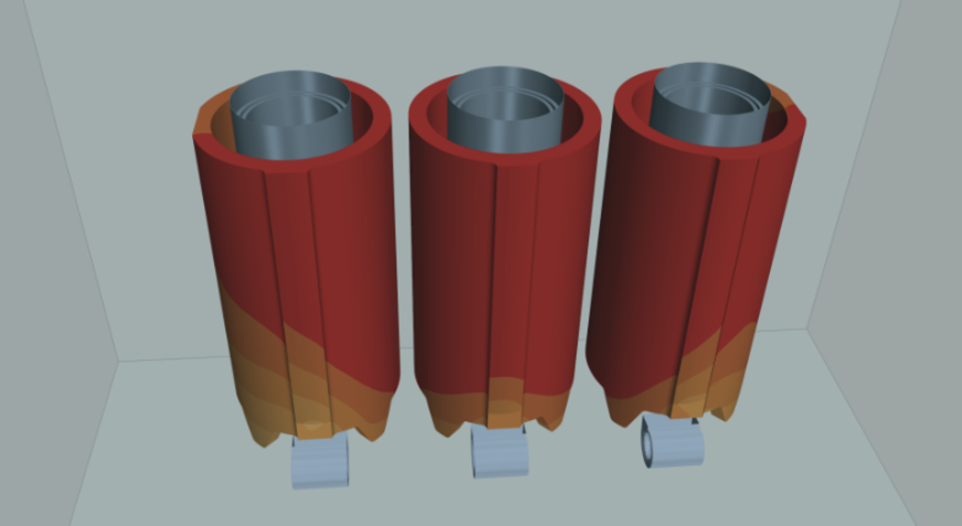
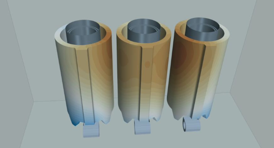
When the fans are switched off, the transformer is cooled only by free convection and the coils heat up considerably. Due to the close arrangement of the coils, the center coil experiences an increased heat load compared to the outer coils, as shown by the temperature distribution on the coil housing in Figure 3.
Already at the outlet planes of the fans there is an inhomogeneous distribution of the velocity, which shows the advantage of CFD simulation in the analysis of such problems.
Now, targeted optimization can be carried out to avoid heat nests without having to build prototypes or even encounter problems during use.
After all, nothing is more annoying than when the transformer burns out or you burn your fingers on it... which brings us back to the electric train.
Do you also have to solve similar thermal problems? Something gets too hot and you don't know if your cooling concept works?
Whether it is a coil, a battery, a printed circuit board or the toy transformer of a Märkline railroad, we know the physics behind it and offer you solutions.
Please feel free to make a non-binding appointment for your CFD simulation.
Your Stefan Merkle

