Structure-borne sound calculation of a ship compressor

Task / Calculation
For equipment in ships, aggregates must not exceed a certain structure-borne sound level. The structure-borne noise is measured using accelerometers at the mounts, i.e. at the base points where the structure-borne noise is transmitted to the ship's floor. Ship compressors are usually reciprocating machines which, like all reciprocating machines, cannot be 100 percent balanced. This means that there are always periodic residual forces that introduce structure-borne noise into the ship. Here, compressor manufacturers have limit curves that must not be exceeded. These limit curves are weighted, i.e. different acceleration levels are permitted for different frequency ranges - usually these are one-third octave levels.
The mass forces and moments from the movement of the connecting rods and pistons are balanced as well as possible by rotating counterweights, so-called unbalance discs. What remains are periodic forces that cause the frame to vibrate. The mounts are relatively soft and can be tuned for force and frequency in the best possible way. As a rule, the natural frequency of the entire, rigidly considered frame is matched with the spring stiffnesses of the mounts so that the frequency is around 7 Hz. This excludes any excitation of this mounting frequency by the slowly rotating ship's shaft ( e.g. 24 rpm = approx. 0.3 Hz) from the ship's bottom.

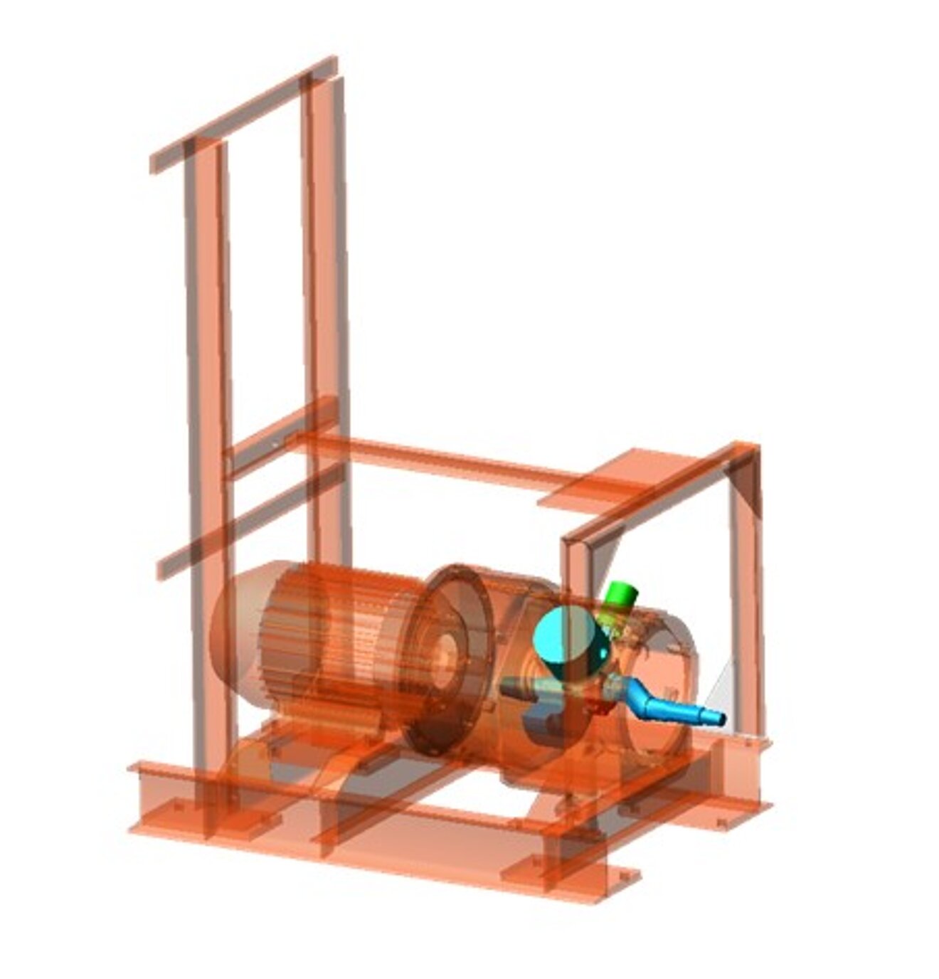
However, if the piston forces hit a natural frequency of the compressor's frame, housing or control cabinet, unwanted vibration overshoots occur. This was precisely the case with the piston machine shown. This became apparent during the test run after construction, when the structure-borne noise levels were far above the permitted values. Since no delivery to the customer could be made without compliance with the limit curves, improvements had to be made now. To do this, however, the cause had to be known so that rebuild measures would also work.
The procedure at that time was as follows:
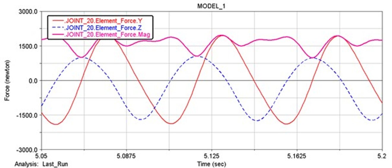
The kinematics of the compressor consisting of crankshaft, piston, connecting rod and unbalanced pulley as well as the loads resulting from the pressures were mapped in ADAMS as a so-called multi-body model. The components were considered to be rigid. This results in the progression of forces and frequencies as a function of time.
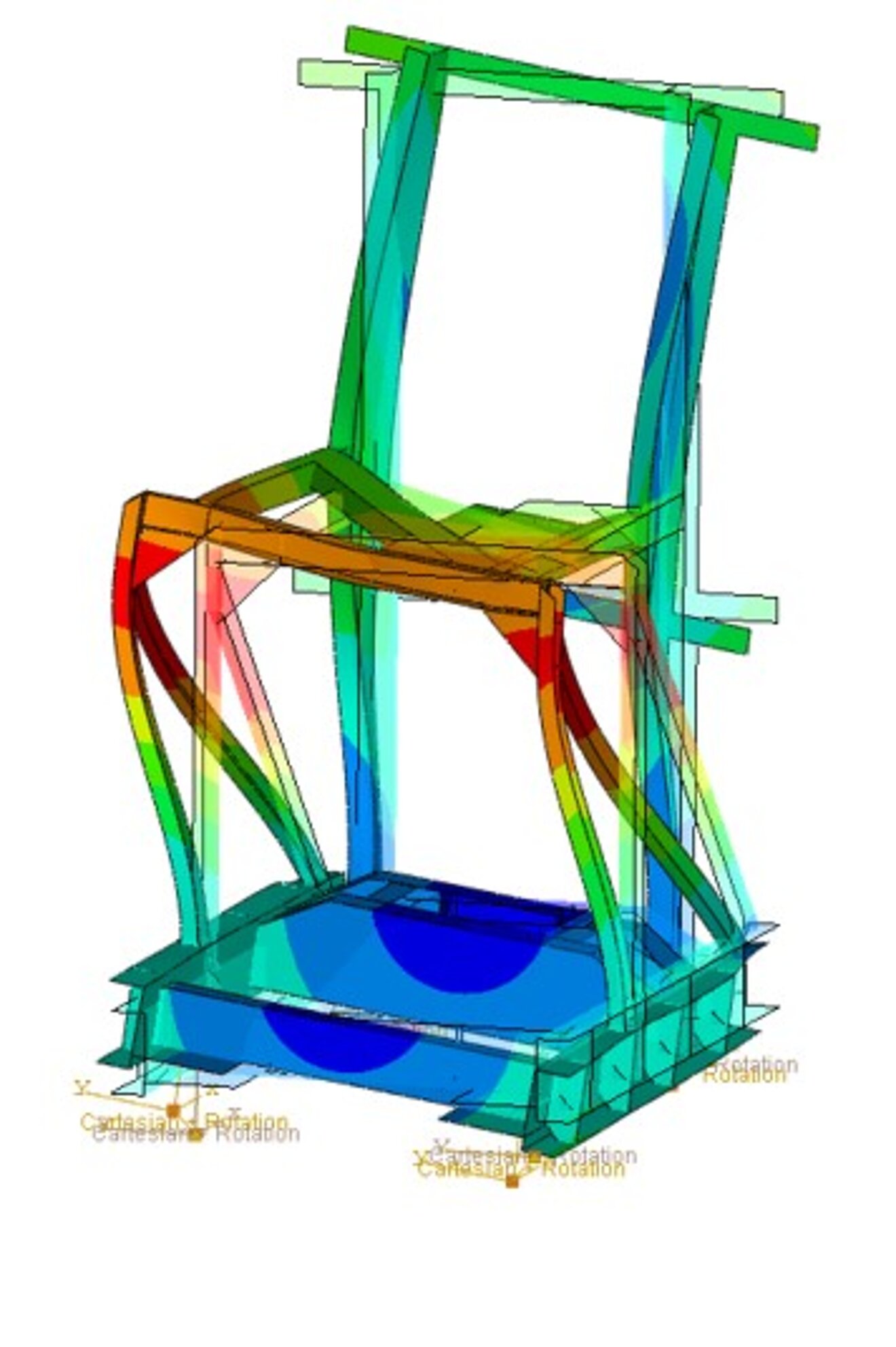
An FE model was created of the entire frame with compressor, electric motor and control cabinet. Components that were not modeled in detail were idealized as mass points and mass inertias at the respective center of gravity. The mount stiffnesses (rubber buffers at the bottom) were linearized. First, the natural frequencies of the FE model were determined and compared with the excitation frequencies of the mass forces. This showed that one natural frequency of the control cabinet was in the range of the excitation frequency.
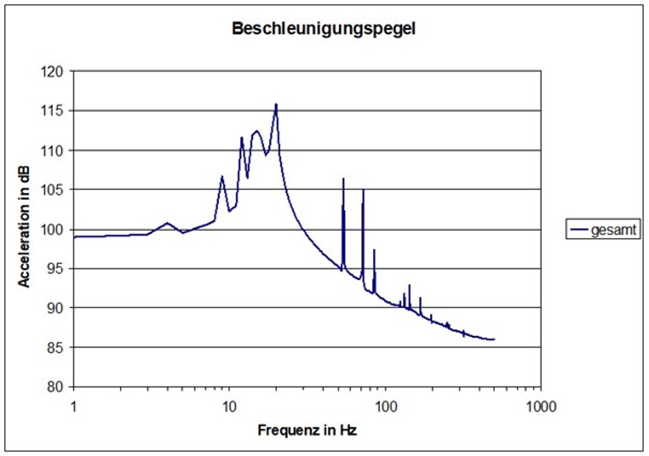
In a transient vibration analysis, the periodic mass forces and moments were now transferred to the FE model and the steady state was calculated for one crankshaft revolution. At the bearings, the accelerations in all axis directions were evaluated and added up to the level. The time response of the accelerations was transformed into the frequency domain by a Fourier transformation.
Result initial state
The resulting acceleration level matched very closely the measured value, which was too high.
Optimization
The frequencies above the limit curve were used to identify the areas that had to be reinforced. By appropriate stiffening measures, in particular of two diagonal struts, the critical frequencies could be avoided in the calculation model or shifted in such a way that they could no longer be excited by the excitation frequencies. Computationally, the structure-borne sound level was now in order. Under enormous time pressure, the stiffeners were installed in the frame and then measured in the test. Here, the mathematical predictions were confirmed, the limit curve could be adhered to and the compressor delivered to the end customer.
Outlook, current approach
Nowadays, the detour via multi-body simulations to determine the transient forces is hardly ever undertaken by us. The FEM tools used, such as Abaqus or ANSYS, are now so good that the complete kinematics with all possible nonlinearities and component stiffnesses can be mapped, thus eliminating the need to transfer the forces from one software to another. Another advantage is that force peaks, which result from the rigid components, are mitigated by elastic components and thus the interpretation of the results becomes easier.


