Development of a quick release coupling


The challenge
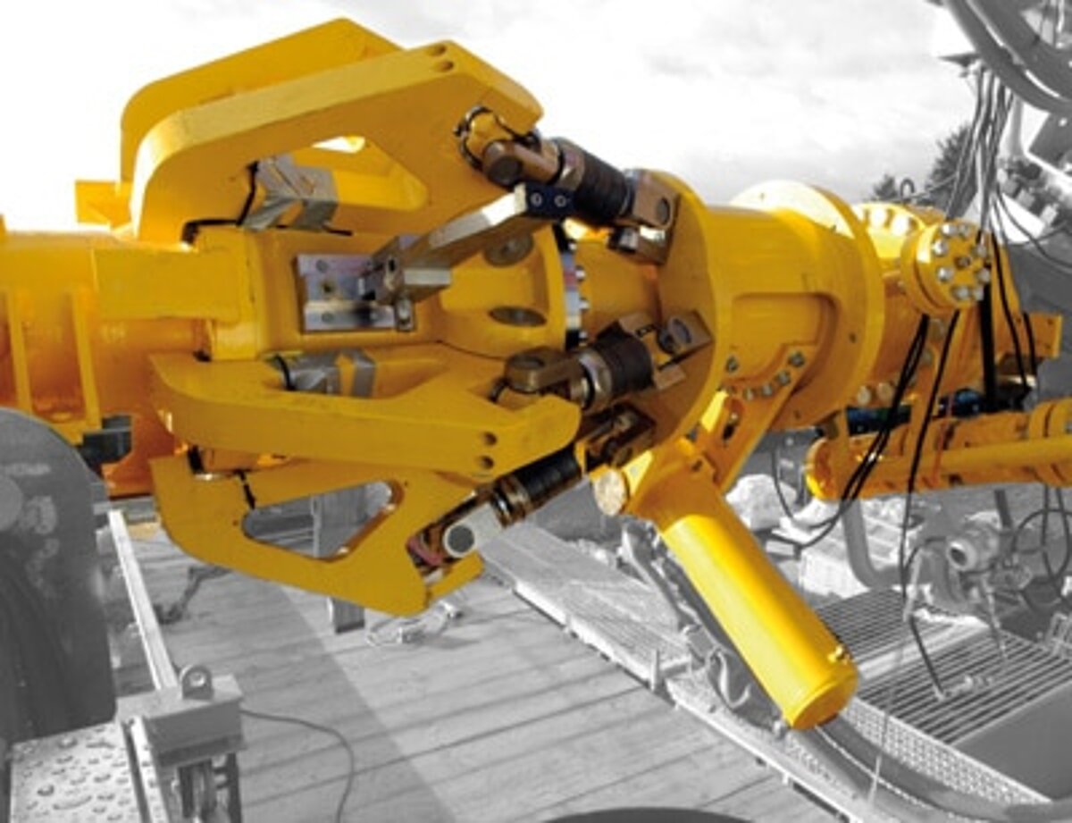
One of our customers, Emco Wheaton, builds loading arms for the oil and gas industry. In 2006, we were asked if we would be able to build an automatic coupling that would automatically connect the unloading arm of an LNG tanker to the shore side. Until then, the flange connections had been made manually with screws, which was an expensive task considering the berthing fees of a ship of about 10,000 € per hour at that time.
The coupling should also be able to provide an emergency disconnection of the loading arms on shore and on the ship within two seconds in case, for example, ropes break and the ship drifts away. There have been a number of accidents here, with ports then in flames.
One problem was that there was no predecessor type. In addition, with an internal pipe diameter of more than 300 mm and a pressure of 225 bar, the forces acting on the pipe were enormous and had to be tamed.
But the real main problem was the time line. Only 6 months from the start of the project to the testing of the prototype. Then 2 weeks for the tests and off to the ship, which was in dock for another 2 weeks for conversion work. A later delivery or a failed test and the customer would not have accepted the coupling as the ship was in service for the next 3 years.
All in all, a sporting challenge that we successfully met.
Prototypes were out of the question due to the tight schedule, 3D CAD, multi-body simulation and FEM calculation were the individual tools to ensure the design for functionality and service life.
To make matters worse, the material had to be ordered after only 3 months, since the claws are highly stressed parts, which had correspondingly long delivery times.
Task / Calculation
For product development and calculation, the project was summarized as follows:
- Development of a quick release coupling for a loading arm.
- Extremely short timeline (no time for prototypes and trials)
- Completely new development, no previous variants available
- Completely virtual product development
- High pressure and large diameter
- Emergency disconnect properties
- Compliance with applicable standards (OCIMF) and acceptance by BV (Bureau Veritas)
The project was carried out by a design engineer and a calculation engineer.
The moment of truth
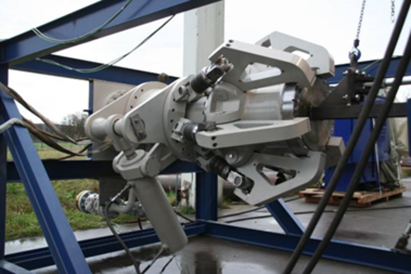
In time for November, all components were delivered to Emco Wheaton and assembled in a test stand. BV's test called for the rapid separation process to be tested with air on a blind flange.
Except for a destroyed test stand that could not handle the kinetic energy of the 100 kg blind flange projectile, the coupling worked flawlessly.
Procedure
The procedure was as follows:
Research into which areas already had similar solution concepts (for much smaller diameters and pressures).
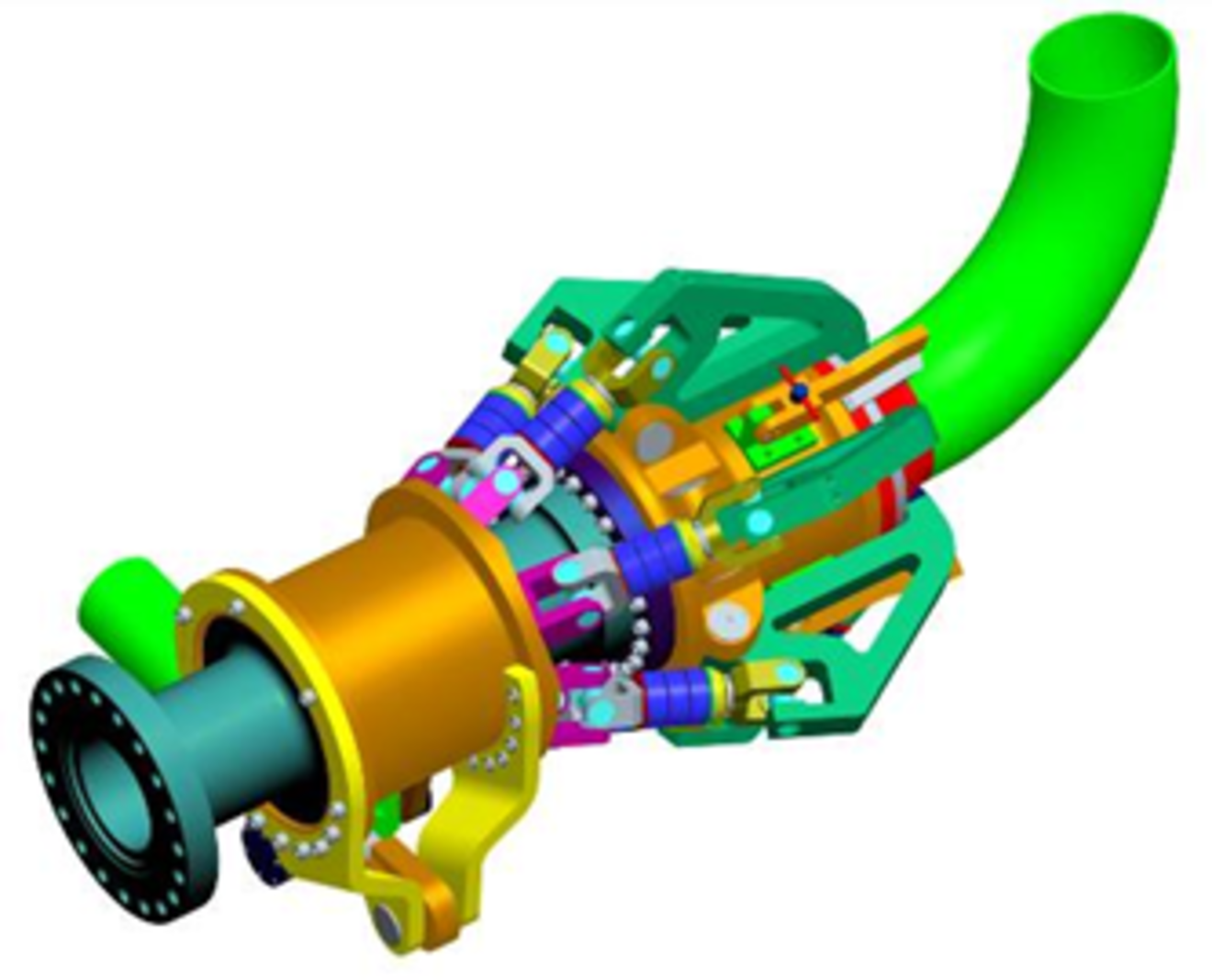
Drawing up a rough concept of how the friction-locked flange connection can be made using hydraulically operated claws.
Rough dimensioning of the claws and the entire construction.
Investigation and determination of critical areas.
Obtaining quotations from potential manufacturing companies.
Investigation of the closing behavior and force curves via multi-body simulations (MBS).
Optimization of claws and selection of materials via automated optimization algorithms (shape optimization of notch stresses).
Flow simulations of the behavior of the enclosed gas volume during emergency separation supplemented the investigations. Here, it was necessary to check whether an explosive mixture could arise.
Completion of the 3D design and derivation of the manufacturing drawings.
Commissioning of the parts.
Installation and operation
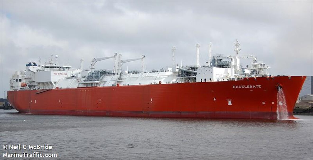
A short time later, the clutch was installed in the Excelerate and has been doing its job there ever since.
The cup springs still had a problem after 2 years due to the salt air, which could be solved by a modified design.
In the meantime, a 2-digit number of such clutches have been built and are in use.


