Hydrogen
![[Translate to English:] Konzept Elektrolyseur Merkle CAE [Translate to English:] Konzept Elektrolyseur Merkle CAE](/fileadmin/_processed_/2/3/csm_Bild1_Konzept-elektrolyseur-merkle-cae_319e17c663.jpg)
Introduction
The development of electrolysers and fuel cells is closely linked to the history of electrochemistry. The beginning of these technologies can be traced back to the early 19th century. In 1800, British scientists William Nicholson and Anthony Carlisle discovered the electrolysis of water, a process in which water is broken down into hydrogen and oxygen. This discovery laid the foundation for the development of electrolysers. At the same time, the Swiss scientist Christian Friedrich Schönbein developed the concept of the fuel cell in 1838 by demonstrating the electrochemical conversion of hydrogen and oxygen into electrical energy. Sir William Grove later refined this concept in 1842 and built the first practical fuel cell. The 20th century saw significant advances in both technologies, particularly through research into the hydrogen economy and efforts to find sustainable energy sources. Today, electrolyzers and fuel cells are central components in the development of clean energy solutions and play a crucial role in the transition to a low-carbon economy.
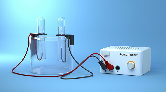
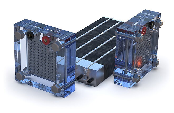
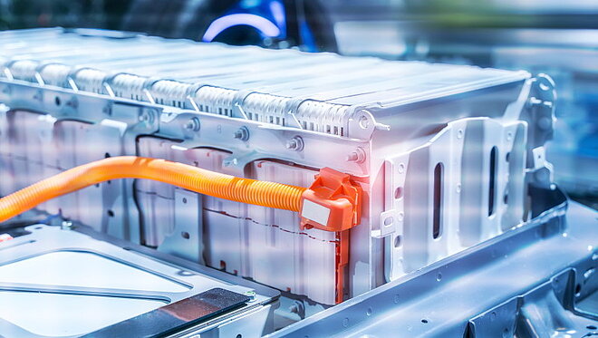
Fuel cells and electrolysers are two sides of the same coin.
What they have in common: Both systems have a similar structure with an anode, cathode and an electrolytic medium. They use electrochemical reactions to either generate energy (fuel cell) or store it (electrolyser).
Differences: The main difference lies in the direction of energy conversion. Electrolysers use electrical energy to generate chemical energy carriers (hydrogen), while fuel cells use chemical energy to generate electrical energy.
In industrial applications, individual cells are assembled in a stack to achieve a compact design.
Merkle CAE has been involved in fuel cell simulation since the end of the 1990s. In recent years, more and more tasks have been added in the field of hydrogen production using electrolyzers.
Requirements
As hydrogen and oxygen form an explosive mixture, the requirements for safety and tightness over the entire service life are important. In addition, a compact design and high efficiency play a major role. Furthermore, the behavior in the event of a membrane rupture must also be evaluated. Does a local explosion in a cell lead to an explosion in the entire stack?
In addition to the issues mentioned, the temperature distribution resulting from the current density distribution in the cell is also important.
The tasks that Merkle CAE deals with in the design of electrolysers and fuel cells are described below using a simple electrolyser. As the topics are similar, no distinction is made below between fuel cells and electrolysers.
End plate rigidity and tightness
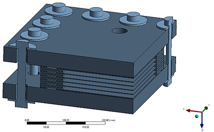
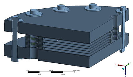
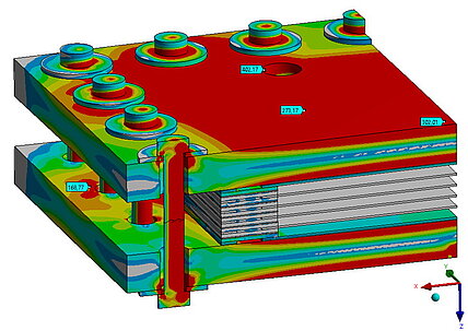
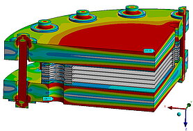
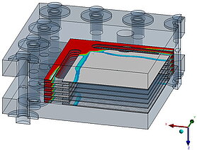
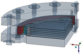
The individual cells of a stack are held together by end plates and pretensioned using screws and disk springs.
The end plates can have different shapes:
There must also be sufficient sealing between the individual chambers. Depending on the materials, the sealing behavior over time due to creep effects must also be analyzed.
These FEM tests can be used to compare and evaluate different concepts. Demonstrators in the laboratory can also be scaled up to large applications in the megawatt range. While the pressures for fuel cells are usually between 1-7 bar, they are between 1-50 bar for electrolysers. This means that, from a certain size, they fall under the rating regulations for pressure equipment in accordance with AD2000, DIN EN 13445 or ASME. The pressure shell can therefore be designed as a pressure vessel. The strength behavior under explosion loads can be determined either on the basis of conservative estimates or more precisely after determining the explosion loads using CFD simulations (see below) in accordance with DIN EN 14460.
Flow analysis, uniform distribution and flow field
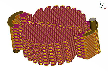
The flow through the stack also plays an important role in terms of efficiency. The flow through all cells should be as uniform as possible in order to enable a compact design for a given output.
The aim of a cell flow is to ensure that the pressure losses in the flow are relatively low and that the installation space is utilized.
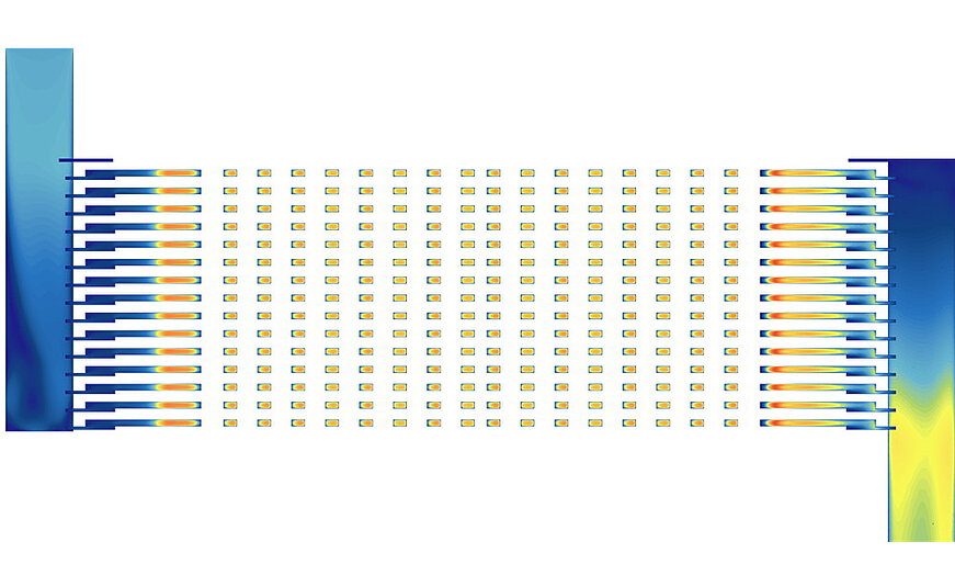
The aim of the entire flow is to ensure that all cells are flowed through evenly.
Temperature distribution and current density distribution
Temperature distribution is of crucial importance for fuel cells, as it has a major impact on the efficiency and service life of the cell. The chemical reactions in the cell take place faster at higher temperatures, which increases performance. An even temperature distribution is important to avoid local overheating. In proton exchange membrane fuel cells (PEMFCs) in particular, the membrane must be sufficiently moistened and kept at a certain temperature to ensure good proton conductivity. Excessively high temperatures can dry out and damage the membrane. In addition, the materials in the fuel cell have optimum operating temperatures; high temperatures can shorten their service life, while temperatures that are too low slow down the reactions and reduce efficiency. Efficient heat management ensures even temperature distribution and prevents hotspots that could damage the cell. The optimum temperature range varies depending on the cell type: PEMFCs work best between 60°C and 80°C. Overall, controlling the temperature distribution is crucial to ensure maximum efficiency and service life of the fuel cell.
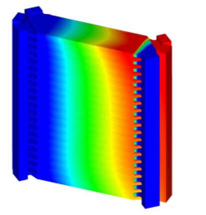
Temperature distribution and current density distribution in fuel cells are closely related. The chemical reactions that generate electricity also produce heat, so areas with a higher current density generate more heat. This leads to uneven temperatures if the heat is not dissipated effectively. The proton conductivity of the membrane, which is crucial for electricity generation, depends on the temperature. At optimal temperatures, conductivity is higher, resulting in a more uniform current density. Uneven temperatures can dry out the membrane, reducing conductivity and therefore current density. In addition, uneven temperature distribution can cause hotspots that degrade the material faster and reduce the efficiency of the reactions. Therefore, temperature and current density distribution influence each other. A uniform temperature distribution helps to keep the current density even and maximize the efficiency and service life of the fuel cell.
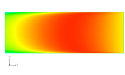
Moisture is also important in a fuel cell because it helps to keep the membrane inside the cell functional. This membrane enables the transport of ions, which is necessary for the chemical reactions that generate electricity. If the membrane becomes too dry, it can crack and the efficiency of the fuel cell decreases. On the other hand, too much moisture can lead to flooding and block the reaction surfaces. A balanced humidity level therefore ensures optimum performance and longevity of the fuel cell.
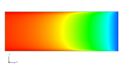
Multiphase flow, water separation, gas bubbles
The CFD (Computational Fluid Dynamics) simulation of several phases (gas, water) in fuel cells and electrolyzers is complex because it has to take various complex aspects into account. First of all, it requires consideration of the different physical properties and behaviors of each phase, such as density and viscosity, as well as their interactions. These interaction models, for example the dissolution of gas in liquid or the rising of bubbles, are very complex and require many calculations. In order to capture these phase interactions accurately, a very fine grid resolution is required, which greatly increases the number of calculation points. Finally, the large number of necessary calculations and the fine resolution require significant computing power and memory resources to deliver accurate results. These factors make the simulation time and resource intensive.
But here too, Merkle CAE can provide support with suitable approaches.

Both phases can be considered in the simulation.
Electrochemistry, comparison between experiment and calculation
In a fuel cell, hydrogen (H2) and oxygen (O2) are converted into water (H2O) through an electrochemical reaction. In the process, hydrogen is split into protons and electrons at the anode. The protons travel through a conductive membrane to the cathode, while the electrons flow through an external circuit and supply electrical energy. At the cathode, the protons and electrons react with oxygen to form water. This reaction continuously generates electricity, heat and water.
The electrochemistry is strongly linked to the temperature in the cell. It therefore makes sense to compare this value when reconciling the experiment and the calculation.
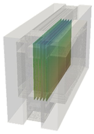
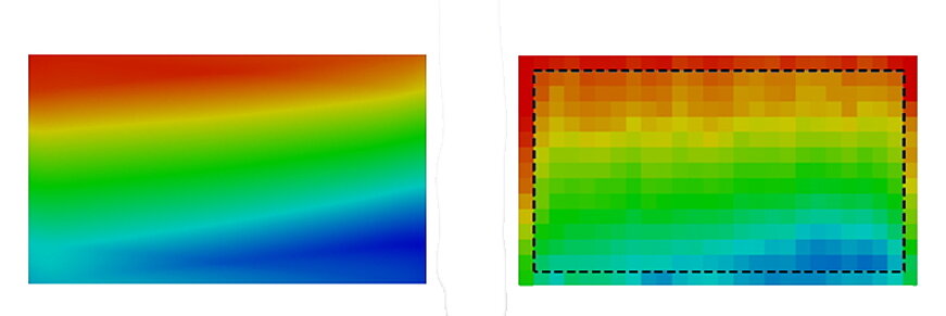
The calculation model shows very good agreement with the values measured in the test.
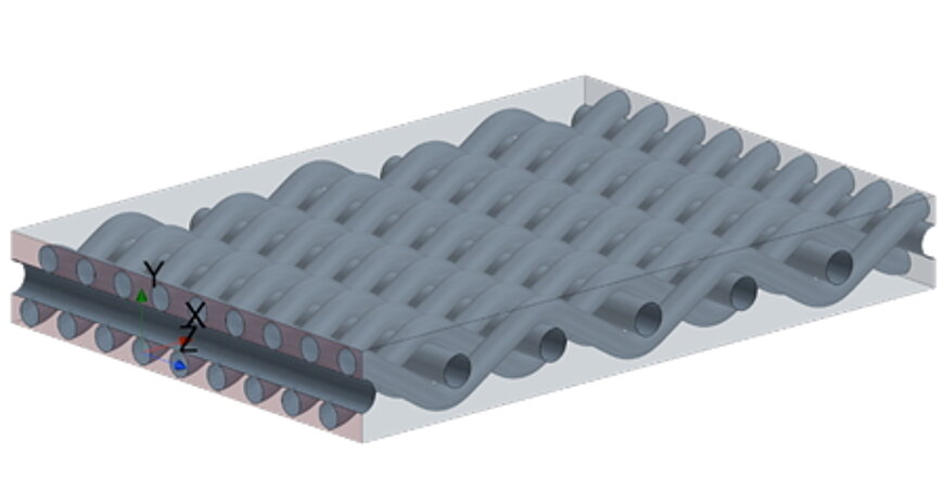
Characterization of fabrics and metal foams using CFD simulations
Fabrics or foams are also increasingly being used for the electrodes in electrolysers. The behaviour of these materials can also be observed using CFD analyses with regard to the characterization of porosity for more complex models.
Explosion calculation via CFD
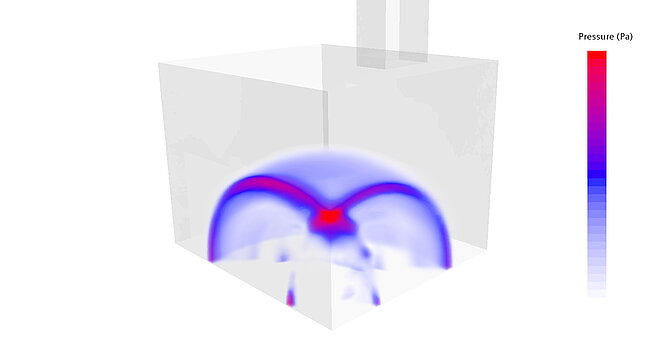
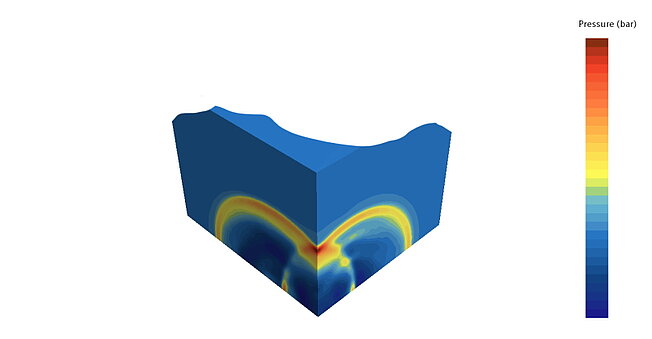
The explosion loads can be described more precisely using CFD simulations that take the reaction kinetics into account. The scenarios to be investigated depend on the requirements that need to be tested.
Merkle CAE has relevant experience here, both with explosions in one or more cells and with explosions within the channels. The resulting pressure distributions can be transferred to the FE model as time functions and evaluated for the actual verification. In particular, tightness is also a decisive evaluation criterion here in order to limit explosion sources locally.
The test spaces can also be evaluated.
Summary and outlook
The development and optimization of electrolysers and fuel cells is similar, as both are based on electrochemical reactions. Electrolyzers use electrical energy to produce hydrogen, while fuel cells use hydrogen to produce electrical energy.
Simulation plays a crucial role in improving these technologies by analyzing the temperature and current density distributions that affect the efficiency and lifetime of the cells and whether the system is mechanically tight. A uniform temperature distribution is important to avoid local overheating and ensure membrane conductivity. The CFD simulation of multiphase flows is very complex and requires considerable computing resources. Further developments are currently taking place here in order to better understand even complex relationships and to solve them with more powerful computers in the future.
Overall, the challenges of tightness, heat management and flow distribution as well as the behavior of local explosions in the stack are decisive for the performance and safety of electrolysers and fuel cells.
Keywords
- Anode
- Fuel cell
- CFD simulation
- Characterization
- Pressure
- Pressure envelope
- Electrochemistry
- Electrolyzer
- End plate
- Explosion
- Flowfield
- Uniform distribution
- Cathode
- Contact pressure
- Porosity
- Oxygen
- Temperature
- Hydrogen
