Belt lift table

Using the example of an automatic parking system, it will be shown how multi- or rigid-body simulations (MBS) can be used to solve specific kinetic or kinematic tasks. Automatic parking systems transport vehicles from the entry level to the different parking levels. In the case considered here, the parking garage is cylindrical, and the vehicles must additionally be rotated on a platform so that the pallet can be pushed into the corresponding parking space.
As a solution concept, a so-called belt lift table was used here to overcome the height differences. The lift table consists of two pairs of scissors that can be moved via roller-cam pairs. The belt pulls the rollers, which can be moved along the scissors, against the cam discs as in a cable pull, thus pushing the scissors apart. The belt has a load-bearing function. On the one hand, it must be ruled out that the permissible belt forces are exceeded, and on the other hand, the holding torque of the electric motor must not be exceeded, otherwise the entire device will collapse.
The calculations were carried out with PRO/MECHANICA MOTION. For this purpose, the geometry of the cam plates was taken from existing CAD data and the model with the position of the hinge points in the extended state was created as a 2D model. This assumption is permissible, since it can be assumed that all four belts distributed over the table width bear uniformly. The resulting forces must be converted accordingly.

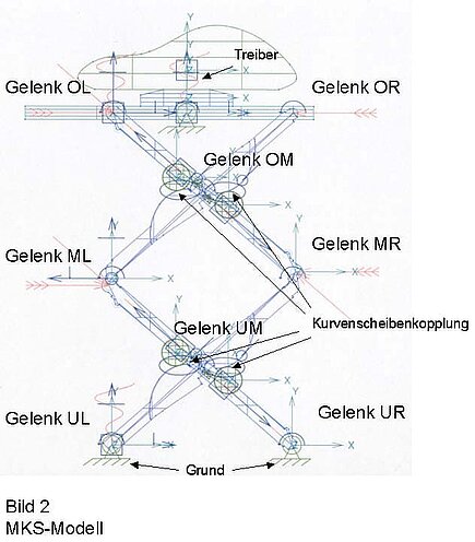
Figure 1 shows the MKS model with designation of the individual components. The designation of the individual bearings can be taken from Fig. 2. The MBS model and the assumptions are described in more detail below.
FMD model
Since the forces in the joints of the lift table and in the belt increase sharply in certain positions of the table, considerations were made to relieve the joints and the belt with the aid of pneumatic tension cylinders.
With the aid of multi-body simulation, the kinematics and the force curve in the belt and in the joints were analyzed and the position and optimum characteristic values of the pull cylinders were determined.
The calculations were carried out using PRO/MECHANICA MOTION.
For this purpose, the geometry of the cams was taken from existing CAD data and the model with the position of the joint points in the extended state was created as a 2D model.
This assumption is permissible, since it can be assumed that all four belts distributed over the table width bear uniformly. The resulting forces must be converted accordingly.
Figure 1 shows the MBS model with designation of the individual components.

The designation of the individual bearings can be taken from Fig. 2.
The MBS model and the assumptions are described in more detail below.

1. all bodies [1] are considered as rigid.
2. the masses are idealized as point masses in the center of gravity of the bodies.
3. the belt force is considered to be constant in the entire system (no friction).
4. the wrap of the belt on the trolleys is assumed to be constant at 180° (the reaction force is twice the belt force).
5. the reaction forces of the belt deflections are taken into account by external forces.
6. all joints are considered frictionless and ideal.
7. 4 cam plates and rollers are included in the model. The cams are fixed to the shears running from the lower left to the upper right. The rollers are movable along the shears running from bottom right to top left. Frictionless, rigid couplings have been described between the cam plate and rollers, which do not allow the roller to lift off the cam plate.

8.A drive (driver) with a specified, constant speed was applied between the base and the upper frame. An empirically determined value is used as the belt force. The resulting residual force in the drive is measured, averaged over existing values and calculated with the belt force in such a way that the auxiliary force converges towards the value 0.
9.The total travel distance of the drive is 5160 mm.
10. the velocity curve during start-up was smoothed to facilitate the convergence behavior of the model.
11. the total stroke is reached after 13 seconds (see Fig. 4).
The initial position for the model is the upper position. 13.
13. the belt loads outside the rollers were applied as external loads at the deflection points.
14. the load arrows with springs are directionally fixed [2], the loads without springs are body fixed [3].
15. the force amount corresponds to the time-dependent belt force determined in the drive.
The calculations were performed dynamically, taking into account the inertia forces, using an implicit time integration method.
Results

Fig. 3 shows the two extreme positions of the lifting table. The specified course of the height over time is shown in Fig. 4.
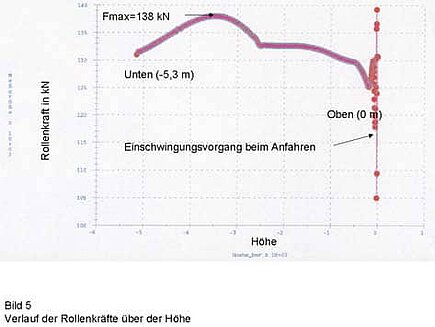
Fig. 5 shows the course of the roller forces over the height. The course of the forces, which should ideally be constant, shows that the cam plates are not exactly matched to the kinematics. This is due to the fact that, for manufacturing reasons, a shape was selected that is composed of two circular arcs. At the transition between the two arcs, a kink in the course of the forces can be observed (Fig. 5).
During startup, the model must be accelerated from 0 to the constant traverse speed in one time step. This explains the transient processes (at height 0), which, however, are not to be expected in reality, since the acceleration of the drive motor is also finite.

The bearing MR and the two middle bearings UM and OM show the highest forces occurring in the retracted position (see Fig. 6). The belt force increases to about 58 kN in the retracted condition. Since the permissible belt force is 60 kN, there is no longer sufficient safety here for the system to operate permanently. Furthermore, the joint forces in the bearings of 175 to 180 kN are also too high, which would result in a redesign of the shears.
The idea was to use additional pneumatic tension cylinders acting between the trolleys to relieve the joints and the belts. The problem in this context is the risk that the dead weight of the lift table without the weight of the vehicle is no longer sufficient to move the system to the lowest position.
Mathematically, this means that the belt forces become negative. Since a belt cannot transmit compressive forces, the system would no longer function.

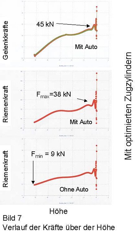
On the basis of several studies in which the articulation points of the tension cylinders and the spring characteristics were varied, an optimized constellation was found with the aid of the multi-body simulation. The belt forces could be reduced to 38 kN in the loaded condition, and the minimum belt forces are still sufficiently large enough at 9 kN without loading.
The maximum joint forces were reduced from 180 kN to 45 kN. Thus, the safety of the system could be ensured with a reasonable effort without limiting the function.
Multi-body simulation proved to be a suitable tool for better understanding the kinematics, finding critical zones and deriving suitable measures for optimization when simulating the lifting table.
[1]Body: In this context, any entity that can be considered rigid in itself and is kinematically connected to other bodies via so-called joints.
[2] Directionally fixed: The orientation of the load vector in the global coordinate system remains the same.
[3] Body-fixed: The orientation of the load vector in the local coordinate system of the body remains the same. Here: The load direction always acts in the direction of the shear.