Optomechanical systems
![[Translate to English:] header-merkle-partner-optomechanik-header [Translate to English:] header-merkle-partner-optomechanik-header](/fileadmin/_processed_/2/a/csm_header_optomechanik_satelit_16863fc054.jpg)
Introduction
Optomechanical systems are combinations of optical and mechanical components. Both components are often supplemented by electronic or electromechanical components, which are used for control and regulation. Examples of optomechanical systems are sensors, mirrors, lens arrays, target acquisition devices, cameras, range finders, lithography optics, LIDAR, periscopes, distance sensors, etc.
The accuracy requirements of such systems must be met under sometimes very harsh conditions, e.g. sensors or optics in automobiles, aircraft, drones, rockets and ships.
In stationary systems, e.g. component measurement by digital measuring machines, the measurement accuracy is already influenced by small temperature changes or vibrations of the foundation. The same applies to lithography optics, whose imaging accuracy is negatively affected by the smallest disturbances.
The tasks for simulation can thus be divided into three main subject areas:
- Distortion due to assembly, e.g. screw connections
- Thermal distortion of the optical axes due to temperature changes and the resulting thermal strains
- Displacement of the optical axes due to accelerations, oscillations, vibrations, spectral loads or shock loads
- Evacuation simulations and filling simulations of the units
Especially shock loads, e.g. firing a shot at a telescopic sight, can damage the mechanics. Strong vibrations, e.g. in optomechanical instruments of a satellite during a rocket launch, can cause damage to the mechanics or loosening of solder connections in the electronics.
Assembly simulation / simulation of the warpage of casting compounds
During assembly, the pretensioning forces of the screws, the curing of adhesives or potting compounds can cause undesired expansion in the assembly, which leads to a displacement of the optical axes. This influence can be investigated and evaluated by means of an assembly simulation. However, since these residual stresses are frozen and usually do not change, they can often be corrected without problems when calibrating the optics.
Simulation of the thermal distortion
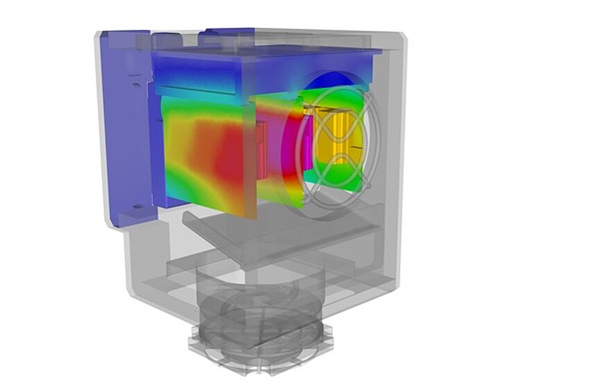
More critical are changes to the system during operation. First and foremost, thermal influences should be mentioned here, which are caused by heating of the electronics or the servomotors, the laser light or by changes in the ambient conditions (solar radiation, ambient temperature).
The thermal distortion can be simulated either stationary or transient, i.e. time-dependent.
There are two steps in the simulation here:
- The determination of the temperature field (stationary) or the temperature fields as a function of time.
- The determination of the deformation of the optical axes due to the thermal strains for one or more points in time.
All non-linearities such as the temperature dependence of the thermal conductivity, the density, the heat capacity, the coefficient of thermal expansion can be taken into account. Likewise, the heat transport by radiation can be included, which behaves non-linearly.
1. temperature calculation
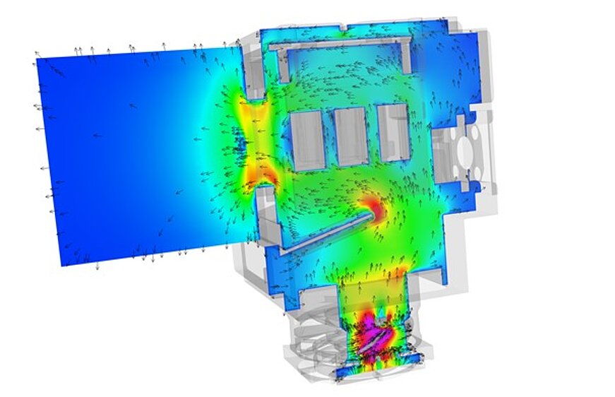
The temperature fields can be determined either by a thermal calculation in a FEM model on the basis of boundary conditions (ambient temperature, heat transfer values for free convection or forced convection from test data, e.g. the VDI Heat Atlas) or also directly in a CFD model on the basis of flow simulations. The flow simulation method is usually more accurate, but also somewhat more time-consuming. Here you have to decide from case to case what is the right way. If, for example, optomechanical systems are clad and the requirements for the accuracy of the temperature fields are very high, there is no way around a CFD calculation.
Radiation effects can be taken into account in both FEM and CFD models.
A distinction is made between external heat sources, e.g. from solar radiation, and internal heat sources (power loss from electronics, electric motors, PSUs, lasers).
The current heat loss (Joule's heat) can also be determined very precisely via an electrical simulation.
2. thermomechanical calculation
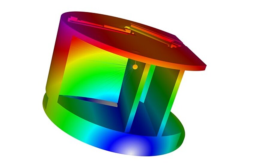
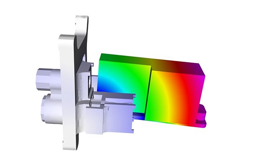
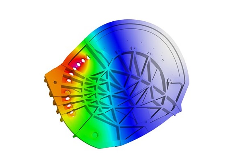
The thermal distortion is calculated using a thermomechanical calculation in the FEM model. The stationary temperature field or the transient temperature fields, which are either determined directly in the FEM model or transferred from the CFD analysis, serve as load cases here. The displacement or rotation of the position of the lenses and the optical axes can be calculated from this and compared with permissible values.
Superposition with any other static and dynamic loads (see below) is also possible at any time.
Static loads
Static loads are constant accelerations. The simplest example is the consideration of the dead weight due to the acceleration due to gravity. Different positions of the assembly in space already result in displacements of the optical axes here and can be determined statically by calculating the assembly on an FEM model.
Simulation of the dynamic behaviour
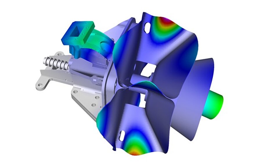
Every structure deforms when exposed to oscillations, vibrations or shock loads. An example of this is excitation during transport. If natural frequencies are excited, as can never be completely avoided with random vibrations, the deflections of the optical axes are greater. If high excitation accelerations meet low natural frequencies, this can have a very strong influence on the accuracy of the optical axes.
In the real test, the system is evaluated on a shaking table with harmonic sweep or spectral loads.
In the simulation, the following tools are available with increasing complexity:
- Modal Analysis (determination of natural frequencies)
- Harmonic Response (response of the system to a long uniform sinusoidal excitation)
- Random Vibration (response of the system to a random excitation, PSD spectrum)
- Shock analysis (spectral analysis via SRS response spectrum)
- Transient shock analysis (direct time integration, temporal response of the system to arbitrary, temporal excitations)
With direct time integration, all non-linear effects, e.g. backlashes, stops, non-linear rubber bearings, frequency dependencies of the material, etc. can be taken into account.
Simulation evacuation and filling
High-precision components in the field of lithography often consist of several lenses arranged in series that operate under near-vacuum conditions. A laser passes through the component and the lenses. Through emission, transmission and reflection, the components and especially the lenses heat up. Hydrogen or nitrogen, for example, is used as the environment.
When the housing is emptied or evacuated or when it is filled with a gas, the flow velocities in the area of the lenses must not become too high, otherwise the smallest dust particles can scratch the surface of the lenses.
Both the temperature distribution in the lenses due to the laser and the flow during evacuation and filling to determine the maximum speed are tasks that we represent via flow simulations.
Project examples
Successfully completed projects in our company are
- Lithography machines
- Equipment for the semiconductor industry
- Laser removal equipment for the surveying of buildings
- Laser cutter
- Glass tank
- Periscopes for submarines
- Coordinate measuring machines
- Laser arrays
- LIDAR scanners
- Vehicle cameras
- Single-lens reflex camera
- Aiming tubes for hunting weapons
- Telescopic mirrors
- Sensors Aircraft
- Sensors Helicopters
- Sensors for vehicles
- Satellite optics
- Target acquisition devices fighter aircraft, helicopters
- Target acquisition devices for tanks
- and much more
Summary and outlook
FEM
- Assembly simulation (spring elements, seals, fits)
- Investigation of solid-state joints and spring elements
- Thermomechanical investigations (deformations)
- Modal analysis to determine natural frequencies
- Vibration and fatigue strength (harmonic excitation, sine-sweep, PSD, shock)
- Long-term behaviour of sealing elements and plastics (creep + relaxation)
- Accuracies in deformations up to 1 nm
- Tolerance investigations (e.g. of bonded joints or inhomogeneities in mass and E-modulus)
- Chemical pre-stressing of glasses
- Transfer of deformation fields for optical analysis.
CFD
- Thermal simulation considering convection, radiation, heat conduction, heat pipes, active cooling
- Evacuation and filling simulations
- Condensation on optics
- Particle simulation (e.g. keeping clean and removal of dust particles)
Benefit
Whether in metrology, in the semiconductor industry or in optical devices and cameras - opto-mechanical or opto-electronic assemblies are used in every case. Ever greater accuracies are required with regard to the optical elements. In addition to manufacturing tolerances, thermomechanical effects or vibration have a great influence on the quality of the components and devices.
The more precise the design, the more difficult it is to carry out test-driven developments.
By means of numerical simulations - thermal, thermomechanical or also dynamic - invisible effects can be made visible and concepts can be evaluated even before prototype construction.
We are happy to help you get your ideas ready for the market.
Merkle & Partner has decades of experience with all of the methods described and has played a significant role in the development and use of the corresponding methods. Benefit here from our unique know-how, which we have built up in cooperation with companies such as Zeiss, Swissoptik, Hensoldt, Schott, Lockheed Martin, HDW, Wittenstein, Leuze and many others.
Norms and standards
- MIL Standard
- MIL-STD 810 D/167
- BV 0230
- BV 0240
- BV 0430/0440
- DIN EN 61373
Keywords
- Response spectrum analysis
- Filling
- Filling simulation
- Natural frequencies
- Natural modes
- Forced convection
- Evacuation
- Evacuation
- Telescope
- Free convection
- Camera
- Laser
- Measuring device
- Optics
- Optical axes
- Optical sensor
- Optomechanics
- Optomechanical systems
- Periscope
- Power Density Spectrum PSD
- Random Vibration
- Response Spectral Analysis SRS
- Shock
- Sine Sweep
- Spectrum
- Spectrometer
- Telescope Mirror
- Thermal Strain
- Thermal distortion
- Thermal shock
- Potting compound
- Vibration
- Target acquisition
- Target tube
